The operators of the M S Norgoma as a museum ship and tourist attraction wanted a new functional and welcoming entrance kiosk for the vessel. Requirements for the kiosk included
- as a reception desk, face the vessel entrance with a clear view of the lobby, gift shop and entrance to the display area.
- as a fully functional work station, accommodate 2 staff and equipment on a level floor for office chairs.
Architects Concept
The concept reflected the curvature of the ship wheelhouse bridge, the ships colours & featured a curved back wall with a picture of the bow of the ship.


The recommended location close to the centre line of the vessel in front of the visitor entrance gave the required views.

The revised floor plan reflected the existing walls and the relocation of the washroom. With the addition of 2 wardrobes behind the kiosk a needed storage space was created.

To provide a level floor for the rolling chairs the kiosk was built on a platform. The height of the front edge of the platform brings the seated attendant closer to the eye level of the visitor for a comfortable contact.

The wall behind the kiosk features a picture of the the Norgoma under steam.

The deep desk behind the transaction counter provides space for a laptop without interfering with visitor reception.

Adequate desk space is provided for two work stations.

The kiosk is complete with drawer space, storage space & wiring.

Fabrication
The architects construction drawings showed the detailed design: a desk circles the kiosk, a transaction counter on 3 sides, a curved wall behind the kiosk., a storage unit, 2 storage drawers and an entrance.


the side desk drawers and

the storage unit.

Plan were also developed for the the front surround of the kiosk,


Once the basic sketches were complete it was necessary to calculate the radii of all the ribs required for fabrication of the curved surfaces by adjusting for the inside or outside of the router cutting bit). Cut numbers were assigned to each radii & to each part.

To insure precise curvatures and precision cutting a special bench was constructed in the ships workshop. The main feature was a arm guiding a router along the chosen radii.


The bench served several functions, in addition to cutting radii.The table height (including a sheet of 1/4 material) is just below the saw level to catch the heavy sheets of HDF being cut. The table has 3 fixed horizontal 2 x 6" members & additional members can be used to support flexible sheets of material.The table was level and when covered by a full 4' x 8' sheet assisted in the many steps in fabrication and assembly of the components of the kiosk.

The 3rd central member crossing the bench was given additional length to provide a pivot point for the moving arm guiding the router.

The moving arm holding the router was made from angle iron salvaged from a old bed frame.

Holes in the arm allow adjusting the radii of the cut..

The holes are drilled & marked for the required cut in the part being fabricated.

A 1" strip of alm. was drilled for the pivot to act as a guide for cutting.

The srtip is used to align centerline of the sheet with the cutting centerline. It also has holes at the cutting radii to assist in cut planning.

When making a cut, thin sacrifice sheets are used to protect the bench members

Secure clamping, safety equipment, shallow cuts & a shop vacuum made the cutting task easy.

Given the need for many parts fitting together accuracy was essential

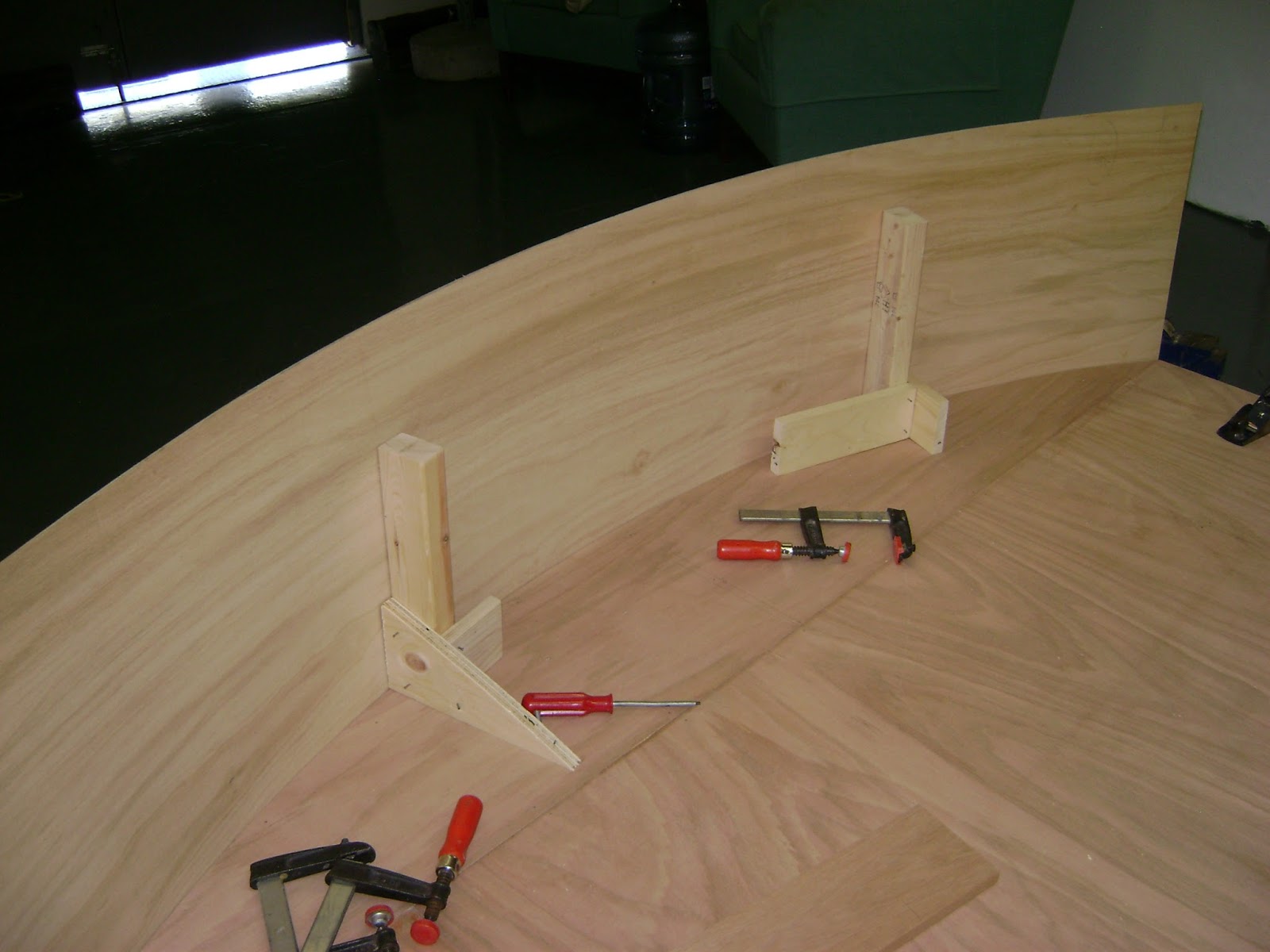
To start building the floor platform a temporary frame was shimmed level, and the floor joists suspended in place above their permanent location.

Two tools were assembled.

The first a tool to mark the joist for cuts to follow the contour of the floor & bring the upper corner to 0 material.

The second to measure the angle of the cut for the joint & legs for the platform.

PL 400 Subfloor & deck adhesive was use for constructing the platform & the kiosk components. Nails were used sparingly for support & alignment while it is bonding. a 3/8 bead, (don't smear) is a permanent bond. PL400 is recommended for heavy-duty construction and engineered lumber. The platform is bonded & bolted to the vessel deck.

The precut curved end of the subfloor is also temporarily installed to measure the legs. The legs are bonded to the subfloor and the assembly put in place.

The sides of the platform were finished with strips of flooring underlay (we were less concerned here with finish). It was temporarily installed for with upright support for the curved portions.
The strips were marked to match the curved floor.

The platform was a convenient location to assemble the curved wall. The two pieces of 1/4" HDF are joined for the front skin & the joint reinforced with small blocks on HDF. 1 x 4" "studs" were used for this non loadbearing wall to lighted the structure so it could be manipulated by one person.
The method to produce all curved components of the kiosk are similar. Supporting members are bonded to 1/4" HDF with PL400.

3/4" Ribs are prepared with the required curvature.

The ribs are beaded with PL 400 and clamped in place.

Reinforcements are then installed, in this case, for the end joints and to take mounting screws through the front skin.

The back skin is install in a similar manner but held in place with a few screws left in place after bonding.

The wall has a compartment with a removable back to accommodate electrical components. Wiring enters the wall through a hole in the top member. The end of the full skin sheet provided the location of a support member for the removable back.

The curved wall and kiosk front were self supporting and were put in place to assist measuring for the additional components.

The components are assembled and the wall moved out of the way for installation of the graphic and work on the kiosk.

The desk surface was prepared for veneering.

Veneer was installed on the surface and inner edge of the desk.

The transaction shelf front and its supports were fabricated with a notch for electrical component wiring and painted before installing on the desk.

The units were placed in the required position on the desk . The location was marked and holes drilled through the desk top for screws to secure the units in place.

Once the transaction shelf was assembled it was finished with veneer and the rest of the kiosk painted, the wall secured and the "interior" components installed.

No comments:
Post a Comment